 Not everything is as it seems. There are lots people out there telling half-truths and whole lies but did you know your FEA software is also doing this? Well, it is, but don’t worry because you can learn to filter out the lies and capture all of the wholesome truth if you know how. Here is a list of reasons why your FEA software is not telling you the truth and what you can do to keep it real! 1. Stress Singularities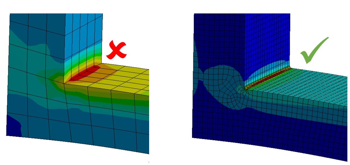 FEA software can’t calculate stress on a sharp corner. Well, it can but I’m afraid this stress is a lie. This is because the stress is calculated as force divided by area, so if the area is infinitely small such as a sharp corner, then the stress could be infinitely high or not real. Solution You can put a fillet radius in the model or you can simply ignore the stress singularities. 2. Rigid Elements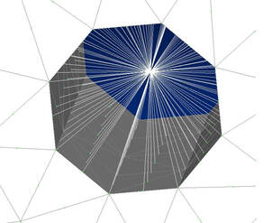 A lot of folks use rigid beam elements to connect components together such as MPC184 or RBE2 but the results in the immediate vicinity of those elements are not real. Any type of rigid elements gives artificially high stress when joined to solid or shell elements. This is not always a problem if you recognise these stresses are not real. Solution Ignore them if you know that region cannot fail. If it could fail then don’t use rigid elements there. 3. Contact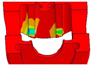 I love contact elements but a word of caution. If you have multiple contact regions, some of them may not be working at all and others could be over constraining the model. Solution You should check each contact region for correct movement, reasonable penetration, load transfer and pressure distribution. 4. Boundary Conditions The most common reason some FEA Reports belong in the dustbin. Boundary conditions are usually assumed but small differences in assumptions can change the results big time. Solution Carry out a sensitivity study by checking the effects of different boundary condition assumptions on the results. 5. Convergence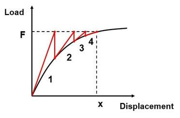 There are various solvers and most will give an error or warning message if the solver did not reach convergence but they don’t tell you if your mesh is fine enough. Solution Check warning and error messages in the solver output file. Do a mesh convergence check. 6. Material Properties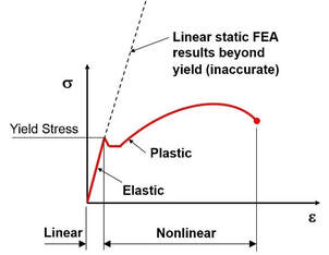 This is the second most common reason some FEA Reports should go straight in the trash. Castings and plastic components often fail because the material properties and behaviour were never understood in the first place. Some materials don’t have much published data and others none at all. Solution Research material properties thoroughly and understand the failure modes of that material. Is it brittle or ductile failure? What’s it like under high or low temperatures? Can it creep, does it age well, could it have defects or porosity? If you can’t find reliable material properties then send test samples to get them. 7. Perfect Geometry Geometry from CAD models is quite perfect. Perfectly straight members, perfectly sharp edges, perfectly placed bolts etc. This is not the case in the real world and can give overly optimistic results. Solution Introduce some imperfections such as misalignment or maybe assume that something is not working exactly as the design intent. 8. Friction I’ve seen engineers arguing over whether the co-efficient of friction is 0.1 or 0.13. The fact is they were both wrong. The range was actually between 0.05 and 0.5 depending on where you get the data from and it varies enormously depending on materials, surface finish and lubrication. So, what is the co-efficient of friction then? Solution If you want to use a coefficient of friction, then check the effects that a range of friction values has on the results. Alternatively, you can assume the best and worst case which could mean frictionless or bonded and go with the most conservative. 9. Loading Some folks put a lot of effort in the FEA modelling then completely guess the applied loads. Others apply loads like the product will always be handled with kid gloves and exactly as the design intent. In the real-world, loads are rarely applied perfectly perpendicular to the face or aligned to your model co-ordinate system. Solution Assume the loads are applied in the worst possible place, at the worst possible angle, over the worst possible area and so on. If it can happen, it will happen sooner or later. The loading should be defined as load cases that cover normal operations, faults and environmental conditions. Some components fail because only one or two load cases were considered and they were not the worst ones. 10. Poor Choices FEA is riddled with assumptions and making the wrong choices can mean one part of the model can be conservative but other parts can lead to overly optimistic results.
Solution Just like boundary conditions, do a sensitivity study to check what effect your assumptions have on the results. Your assumptions may be good but how do you know that for sure? Finally…. There’s no such thing as a perfect FEA model. They’re all wrong but some are useful. Your FEA software maybe telling you porkies but that’s OK provided you can spot them and don’t take everything at face value. It’s good to be sceptical and ask questions. Don’t believe everything you hear and only half of what you see when looking at those stress plots.
0 Comments
Your comment will be posted after it is approved.
Leave a Reply. |
AuthorChris Hall 
Categories
All
Archives
May 2023
|