Stress Theories (von Mises and Max Principal)
When looking at brittle materials most FE Analysts choose Maximum Principal Stress. Brittle materials can be defined as having an elongation of less than 5%. Grey Iron is a good example of a brittle material.
Von Mises Stress is preferred for linear static analysis of ductile materials such as steel. Maximum Principal Stress is often used for fatigue studies of ductile and brittle materials.
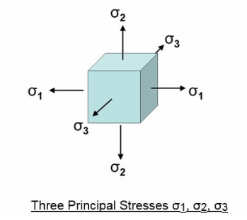
The following diagram shows three principal stresses on a single element.
Von Mises Stress is preferred for linear static analysis of ductile materials such as steel. Maximum Principal Stress is often used for fatigue studies of ductile and brittle materials.
The following diagram shows three principal stresses on a single element.
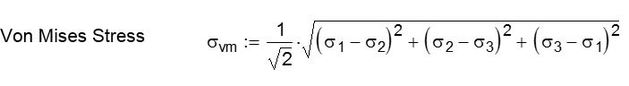
The Von Mises Stress can be found using the three principal stresses as follows;
The direction of the three principal stresses are not necessarily aligned with your FEA coordinate system and they could be at any angle. The Maximum Principal Stress is defined as σ1 and the Minimum Principal Stress σ3.
σ1>σ2> σ3
Your FEA software will typically give you Maximum Principal and Von Mises stress plots so there is usually no need to know all three principal stresses.
σ1>σ2> σ3
Your FEA software will typically give you Maximum Principal and Von Mises stress plots so there is usually no need to know all three principal stresses.