Cantilever Beam Worked Example
This section gives a brief overview of stress analysis and covers;
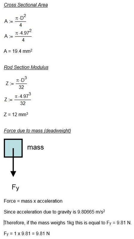
• Force due to mass (deadweight)
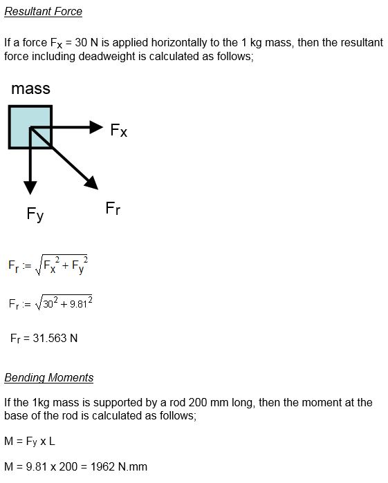
• Resultant Force
• Bending Moments
• Bending Stress
• Shear Stress
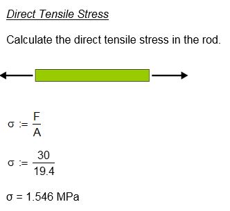
• Direct Tensile Stress
• Von Mises Stress
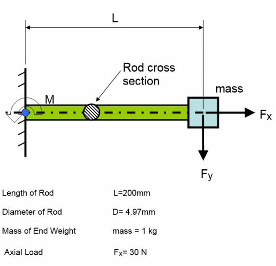
Consider a cantilever circular rod 200 mm long and 4.97mm diameter with a 1 kg mass on one end and a horizontal force (Fx) of 30 N applied to it. Calculate the forces and Von Mises stress in the rod.
• Force due to mass (deadweight)
• Resultant Force
• Bending Moments
• Bending Stress
• Shear Stress
• Direct Tensile Stress
• Von Mises Stress
Consider a cantilever circular rod 200 mm long and 4.97mm diameter with a 1 kg mass on one end and a horizontal force (Fx) of 30 N applied to it. Calculate the forces and Von Mises stress in the rod.
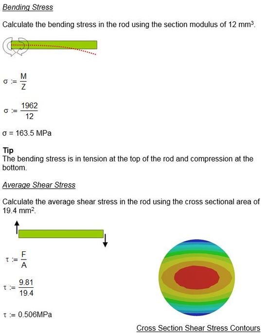
Tip
Average shear stress is frequently used in hand calculations. For a round rod the maximum shear stress will actually be 4/3 x F/A with the peak stress in the centre of the rod. The actual shear stress at the top and bottom of the rod is near zero.
Average shear stress is frequently used in hand calculations. For a round rod the maximum shear stress will actually be 4/3 x F/A with the peak stress in the centre of the rod. The actual shear stress at the top and bottom of the rod is near zero.
Combined Stress
For calculation purposes we can find the Von Mises Stress from the three principal stresses.
The direct tensile stress is in the same direction as the bending stress (top of the rod) so these can be added together for the first principal stress P1.
The shear stress is zero at the top of the rod therefore the second principal stress P2 is zero.
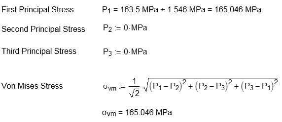
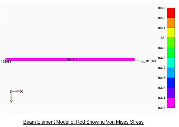
The hand calculated Von Mises Stress was 165.046 MPa and this compares with 164.3 MPa from the FEA model as shown in the plot below.