- Value Design Ltd
- Services
- Projects
-
Finite Element Analysis
- Introduction to Basic FEA
- Units
- Co-ordinate Systems
- FEA Procedure
- Defining Objectives
- Stress Concentration
- Geometry import / clean up
- Meshing
- Material Properties
- Boundary Conditions
- Solvers
- Investigating FEA Results
- Reporting
- Stress Theories
- Cantilever Beam Worked Example
- Pressure Vessel Worked Example
- Shaft in Torsion Worked Example
- Buckling Worked Example
- Bearing (Contact) Worked Example
- Non Linear Material Worked Example
- Portal Frame Worked Example
- BLOG
- FAQ
- CONTACT
Frequently Asked Questions (FAQ) & FEA Snippets
Some of the more frequently asked questions are listed here. This includes some FEA Snippets posted on LinkedIn.
Follow Chris Hall CEng on LinkedIn to join the conversation.
What is FEA?
How much does FEA cost?
Should I de-feature CAD geometry prior to FEA?
What information should I send to you for a quotation?
|
|
FEA Snippets |
|
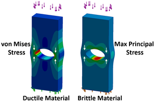
Snippet 1. Should I use Von Mises Stress for Brittle Materials?
Von Mises stress is lousy for brittle materials.
Brittle materials are usually strong in compression but weak in tension.
It’s because brittle materials are prone to cracking, usually at the surface as a result of tensile stress.
Since Maximum Principal stress is tensile stress, this is ideal for brittle materials.
Von Mises stress is good for ductile steel because steel is a similar strength in tension and compression, it can be stretched and squashed.
Since the peak von Mises stress may be in compression, a brittle material may not crack there.
But a brittle material will usually crack at the peak Maximum Principal stress.
Quite often, the peak von Mises stress is about the same value as the peak Maximum Principal stress, and in the same place if they are both in tension.
Don’t forget that some brittle castings have flaws and this also influences where they will crack.
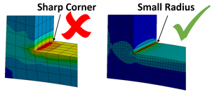
Snippet 2. What is a Stress Singularity?
FEA can't find stress on a sharp corner.
Well it can, but it's not real.
It's called a singularity and the stress values are meaningless.
Furthermore, if you refine the mesh around a singularity, the stress will keep going up. Refine it some more, it will still keep going up. The more you refine, the more the stress increases.
The stress will never converge on a singularity. It's like trying to calculate tensile stress on a point.
Stress = Force / Area of a point = Error
Since a point has no area.
So what shall we do about it?
If you need to know the stress in a corner, put in a very small radius and a fine mesh.
After all, there may be a sharp corner in your CAD model but in the real world, there really is a very small radius anyway.
Better still, design in a large radius if you can.
FEA models built with solid and shell elements are usually riddled with singularities.
You can't put a small radius everywhere in your model but a short distance away from the singularity, the stress is real.
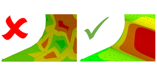
Snippet 3. How much Mesh Refinement is needed?
A mesh that is too coarse leads to inaccurate results in FEA.
If the stress contours appear patchy, this indicates that the mesh is too coarse.
If the stress contours look smooth, the mesh could be fine enough but I'm not sure.
There are better ways to check.
If you compare the averaged and unaveraged nodal results and the stress is about the same for both, this indicates that the mesh is fine enough.
There is an even better way to check.
Compare the stress from a coarse mesh with a fine mesh. Then keep refining the mesh until the stress is about the same for the last two results. This is called a mesh convergence check.
If the last two mesh refinement stresses are within 1% of each other, this is an accurate result.
If the last two mesh refinement stresses are within 5% of each other, this may be acceptable. This depends on what type of analysis you're doing.
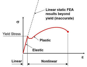
Snippet 4. What is Linear and Nonlinear Material in FEA?
Linear static FEA models are good for steel components up to yield.
Beyond yield, the stress results are meaningless.
But some materials don't have a yield point, such as grey cast iron and this is considered to be a brittle material.
Some plastics have a very smooth 'arc like' stress-strain curve with no visible yield point and a linear static FEA model wouldn't be very good for these materials either.
A good indication of material ductility is % elongation.
As rule of thumb, less than 5% elongation is brittle and more than 5% elongation is ductile.
Structural steel is around 20% elongation and is ductile.
Grey Iron Casting is around 1% elongation and is brittle.
For more accurate FEA, non-linear material properties need to be input into the material database for your model.

Snippet 5. What is Elastic-Plastic Material in FEA?
Three common material models used in FEA are elastic, elastic-plastic and elastic-perfectly plastic.
There’s more to it than this but these three are great most of the time.
The most common is linear elastic and this works just fine for ductile steel if you design below yield, which most of us do.
But if you want to know how much your component will permanently deform if the nominal stress is above yield, then a bilinear elastic-plastic stress-strain curve usually works very well.
Some design codes require a bit more conservatism and they specify an elastic-perfectly plastic model should be used. This will overestimate permanent deformation and it can lead to convergence issues because of the abrupt change from elastic to perfectly plastic at the yield point.
My favourite is bilinear elastic-plastic because it’s simple and I’ve had good correlation with physical test results using this method
Snippet 6. What is Geometric Nonlinearity in FEA?
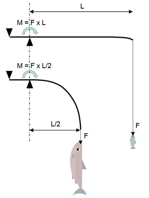
Linear static FEA models are fine for components that are stiff and have stress below yield for most grades of steel.
But linear static models assume small displacements and will give inaccurate results for very flexible components.
So for components that are very flexible, don't forget to select 'Large Displacement' solution for your solver.
'Large Displacement' solution will take longer to solve because it updates the stiffness for each solution step.
Snippet 7. What's the difference between Peak Stress versus Nominal Stress?
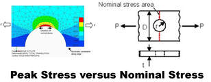
The peak stress in FEA results is sometimes due to stress concentrations, like high stress around a hole.
The nominal stress is the average stress across a cross sectional area, like Stress = Force/Area.
For a mild steel component with a single static load, the peak stress does not significantly affect the overall strength of the part.
If the peak stress is higher than yield, it goes plastic, but a short distance away from the plastic region, it is elastic.
If the nominal stress is elastic, then the mild steel won't fail for a single static load.
If the nominal stress is plastic, the cross sectional area will start to neck and complete fracture is not far away.
It's a different story for fatigue but that's for another day.
Snippet 8. Do Boundary Conditions affect the FEA Results?
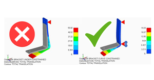
I'm always sceptical about FEA results because I know that poorly applied boundary conditions can have a big effect on the stress and displacement values.
Badly applied boundary conditions are very often the single greatest source of error in finite element analysis projects.
And your FEA software won't give any warnings about poor choices either, it's really down to your own experience.
Snippet 9. What is Modal Analysis?
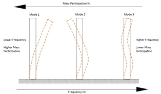
Modal frequencies are measured in Hz and all components have many modes. The first modal frequency is of particular interest.
In general, stiff structures have a first mode that is high frequency and flexible structures have a first mode that is low frequency.
Normally, the first modal frequency also has the most moving mass, sometimes a swaying type motion.
Higher modal frequencies have more of a ripple effect, where less mass is moving but it’s moving faster, like vibrations.
The picture shows the first 3 mode shapes for a column fixed at the base.
You can see that at lower frequencies, more mass is moving.
This is important, since more moving mass results in higher stress.
Remember that there needs to be some driver to excite these modes, otherwise these modes will lie dormant.
That driver could be an earthquake or perhaps a rotating shaft.
Earthquakes are typically in the low-frequency range of under 40 Hz and a rotating shaft on a turbocharger is very high frequency at around 3000 Hz.
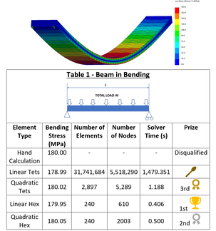
Snippet 10. Which is better, Hex or Tet Elements?
Which type of solid elements are better, Tet or Hex Elements?
It is common knowledge that Hexahedral elements are more efficient than Tetrahedral elements.
There is a downside to Hex elements, it is sometimes difficult to mesh tricky geometry.
So are Hex elements still worth the effort?
I decided to put these to the test with linear and quadratic elements.
I put a long flat bar in bending and checked the stress values using 4 different types of solid elements and recorded the maximum bending stress and the solver time.
The table in the picture shows that the Linear Hex elements were the most efficient and the Linear Tets were the least efficient.
My personal favourites are either Quadratic Tets or Quadratic Hex elements because they both do an excellent job.
Linear Hex elements are OK sometimes but I never use Linear Tets because the results are very poor.
The beam geometry I used was 3000 mm long by 200 mm wide and 50 mm deep. The total distributed load was 40 kN and it was pinned at both ends.
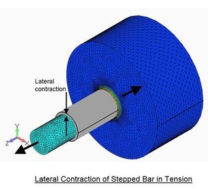
Snippet 11. What is Poisson's Ratio?
Poisson's ratio is a measure of the lateral contraction of a material when under tensile stress in the longitudinal direction.
For most cases, it has little effect on the results but for a few it is significant.
Poisson’s ratio varies from 0.2 for some grades of cast iron to 0.45 for some grades of polythene. It is a required input into FEA models.
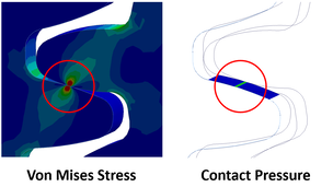
Snippet 12. What is Contact Stress?
Contact stress is Hertzian pressure and can lead to pitting in gear teeth.
Pitting also known as surface fatigue is the most common failure mode for gear teeth and is due to surface indentations ranging from 10 microns to over 1mm in size.
It occurs when repeated contact pressure (stress) exceeds the surface fatigue strength of the material.
To reduce pitting and extend the life of gear teeth, they are usually through-hardened or case-hardened.
Through-hardened gear teeth have constant hardness throughout the entire thickness of the tooth.
Case-hardened gear teeth are softer in the centre but have a thin outer layer that is hardened to provide maximum surface hardness and wear resistance.
Gear teeth that are not through-hardened or case-hardened have very poor resistance to pitting and wear.
It is the contact pressure between the gear teeth that is used to determine if gear teeth are likely to meet the service life requirements.
There are other modes of gear tooth failure but that is for another day.
For other applications such as pins in holes of structural steel, bearing or contact stress is much less important.
This is why some design codes specify bearing stress as Force divided by the projected area of the pin, rather than the Hertzian contact stress.
To find Hertzian contact stress in FEA requires a very fine mesh and considerable analysis effort.
Hand calculations are very often better than FEA for well-known examples of contact pressure but FEA can find contact pressures where textbook equations do not exactly match the application.
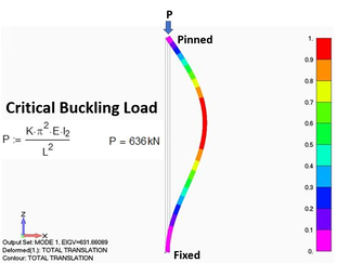
Snippet 13. What is Critical Buckling Load?
Buckling can occur even when the stress in the column is less than the yield strength.
Euler’s formula for critical buckling load is widely used and calculates the maximum compressive load in a slender column that will cause it to suddenly bend or buckle.
The critical buckling load is also called the load factor or eigenvalue for the first mode.
Euler's formula is based on linear buckling whereby the material is isotropic, the load is only applied in the axial direction, the column is straight and slender and there is no other loading from the joints.
FEA models built with beam elements should be a very good match with the calculated Euler's critical buckling load. The example shown in the picture was built with solid elements and was quite close.
The way the column is held at each end has a big influence on the critical buckling load.
In the example shown in the picture, if both ends were pinned, this would approximately halve the critical buckling load.
If the base of the column is fixed and the top of the column is free, like a mast, the critical buckling load would be about 8 times less.
There are other types of buckling such as torsional buckling, lateral torsional buckling and local buckling of individual plates (stiffeners & web) but that’s for another day.
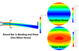
Snippet 13. Where is the Peak Shear Stress in a Round Bar?
Most steel beams don't fail due to shear stress.
They usually fail as a result of either bending or buckling.
The peak shear stress in a round bar beam is in the centre, whereas the peak von Mises stress is at the top and bottom.
The peak shear stress for a round bar can be calculated as 4/3 x F/A.
It is common practice to just use the average shear stress F/A in many cases.
Shear stress is much more important for parts such as dowel pins and connections.
But shear stress is also used along with tensile and compressive stress to find von Mises stress.
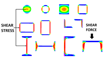
Snippet 14. Where is the Peak Shear Stress in Open and Closed Steel Sections?
Engineers often do hand calculations to find shear stress in various steel sections.
The picture shows that shear stress is concentrated in the centre of solid round and square bars.
It also shows that shear stress is mainly in the plates that are aligned parallel to the direction of the load.
Hand calculations for shear stress sometimes only include the plates that are aligned parallel to the direction of the load for this reason.
The shear stress for an I beam section is concentrated in the web and the peak shear stress is in the centre of the web.
Sections such as Channel and Angle have a shear centre that does not lie on the plates but is offset.
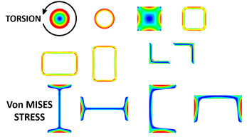
Snippet 15. What Type of Steel Sections are Better for Torsional Loading?
Torsion applied to circular sections results in the peak von Mises stress on the outer surface and these do not warp.
The picture shows a similar trait in a square bar, square and rectangular hollow sections where high stress is observed on the outer flat surfaces. These types of sections have insignificant warping as does angle iron.
Open sections such as I beams (UB), H columns (UC), and Parallel Flange Channels (PFC) are prone to warping.
That’s why the best choice for any member with high torsional loading is circular sections followed by square and rectangular hollow sections.
Torsional loads on a circular shaft result in pure shear stress if no other loads exist.
In this case, the shear stress would be von Mises Stress divided by √ 3.
- Value Design Ltd
- Services
- Projects
-
Finite Element Analysis
- Introduction to Basic FEA
- Units
- Co-ordinate Systems
- FEA Procedure
- Defining Objectives
- Stress Concentration
- Geometry import / clean up
- Meshing
- Material Properties
- Boundary Conditions
- Solvers
- Investigating FEA Results
- Reporting
- Stress Theories
- Cantilever Beam Worked Example
- Pressure Vessel Worked Example
- Shaft in Torsion Worked Example
- Buckling Worked Example
- Bearing (Contact) Worked Example
- Non Linear Material Worked Example
- Portal Frame Worked Example
- BLOG
- FAQ
- CONTACT
