Portal Frame FEA - Worked Example
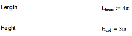
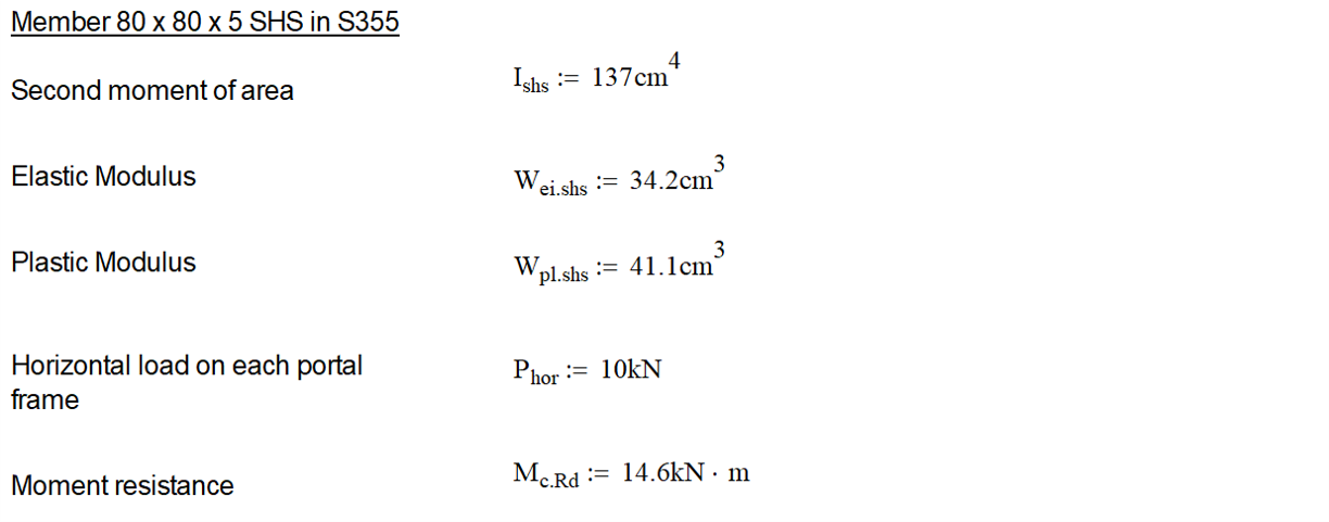
Consider a portal frame 4m long and 3m high built up with 80 x 80 x 5 SHS in S355. Assume the frame is fixed at the base with a 10 KN horizontal load applied to the top corner.
We can calculate the forces and bending moments in the portal frame using the equation shown in Figure 1.
We can calculate the forces and bending moments in the portal frame using the equation shown in Figure 1.
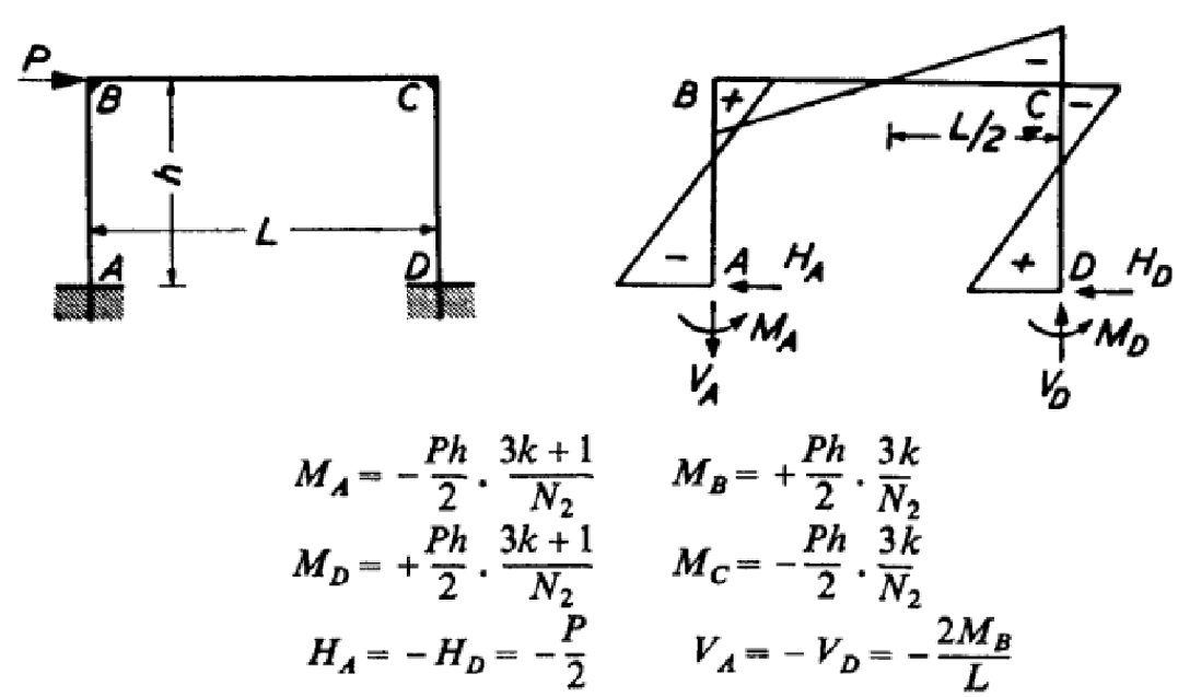
Figure 1 – Portal Frame Reactions Forces and Moments
The Eurocodes specify class 1 sections can use plastic modulus and the SHS is class 1.
The elastic modulus can also be used for conservatism.
Tip
There are numerous tables online which list the section classification and properties below of common members such as SHS, RHS, CHS, UB, UC, PFC etc.
The elastic modulus can also be used for conservatism.
Tip
There are numerous tables online which list the section classification and properties below of common members such as SHS, RHS, CHS, UB, UC, PFC etc.
Once the bending moments are calculated, these are used to find bending stress in the columns using both elastic and plastic section modulus.

Now let’s try the same with FEA using beam elements.
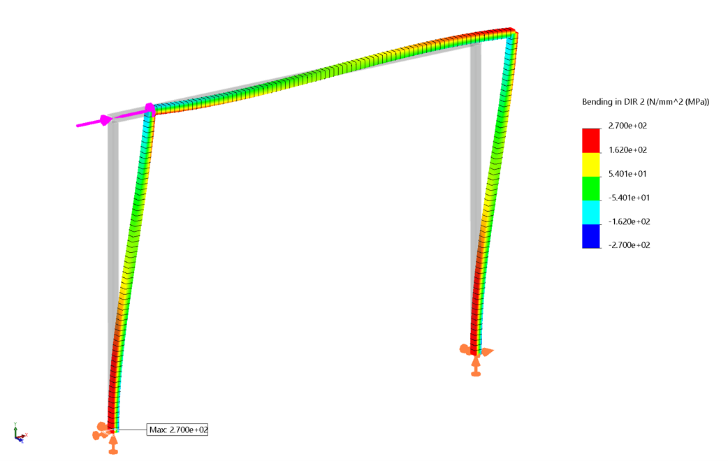
Figure 2 – Bending Stress in Portal Frame
The FEM is set up with beam elements fixed at the base nodes and bonded in the corners with a 10 kN load applied to the top corner node.
The maximum principal stress due to bending in the columns is 270 MPa from the FEA. This compares to 259 MPa from the hand calculation.
The difference is partly because the elastic modulus used in the hand calculation was not exactly the same as the FEA software database elastic modulus.
Now let’s check the bending moments and see how the hand calculation compares with the FEA.
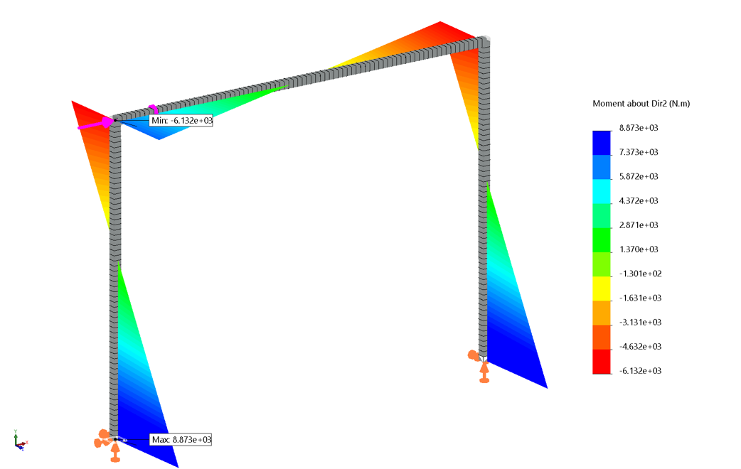
Figure 3 - Bending Moments
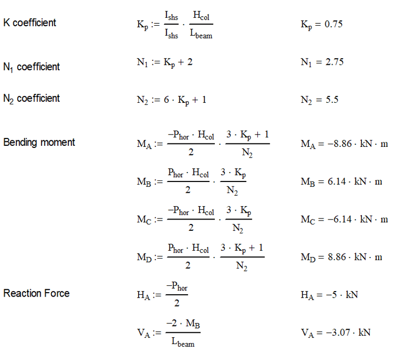
At the base of the columns, the bending moment was 8.86 KN/m from the hand calculation and 8.87 KN/m from the FEA.
At the top corners of the columns, the bending moment was 6.14 KN/m from the hand calculation and 6.13 KN/m from the FEA.
Now let’s have a look at the reaction forces.
At the top corners of the columns, the bending moment was 6.14 KN/m from the hand calculation and 6.13 KN/m from the FEA.
Now let’s have a look at the reaction forces.
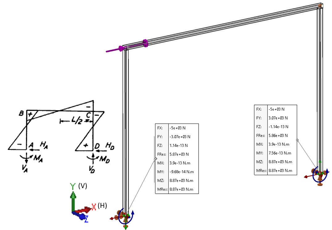
Figure 4 - Reactions Forces
At the base of the columns, the vertical reaction force was 3.07 KN for both the FEA and hand calculation.
At the base of the columns, the horizontal reaction force was 5 KN for both the FEA and hand calculation.
The load input of 10 KN matches the reaction forces at the base of the columns (2 x 5kN = 10kN) as expected.
The FEA results were close to the hand calculation and would have been even closer if the section properties used in the hand calculation exactly matched the default section properties in the FEA software database. There was also some minor number rounding errors but this can be expected.
Tip
If the reaction forces at the base constraints did not match the input forces, then something would be seriously wrong the FEM.