Stress Concentration
In general, hand calculations are often used for finding nominal stress and FEA for peak stress but either method can be used. The following example shows a flat plate with a hole in it and a load applied in tension. The stress is found with hand a calculation and the results are then compared with FEA.
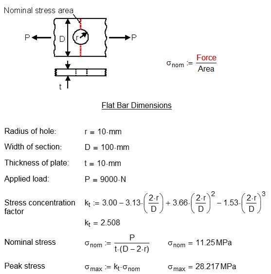
The nominal stress is the average stress over the area in tension
i.e. (D - 2r) x t. The peak stress is on the edge of the hole.
Consider a steel flat bar 100mm wide by 10mm thick with a 10mm radius hole in the centre. A 9000 N load is applied in tension. Calculate the nominal and peak stress on the edge of the hole.
Tip
The nominal stress can be applied to ductile materials such as steel for a single linear static load. This is because stress concentration factors (i.e. peak stress) do not affect the overall strength of the part for single load applications. Peak stress is crucial for fatigue calculations since any stress raisers will significantly reduce the service life of the component.
You can see from the hand calculation that the hole has magnified the nominal stress by a Kt factor of 2.5 times.
Now let’s see the FEA model results. Symmetry has been applied to the model on the centre line and a force applied to both ends to simulate tension.
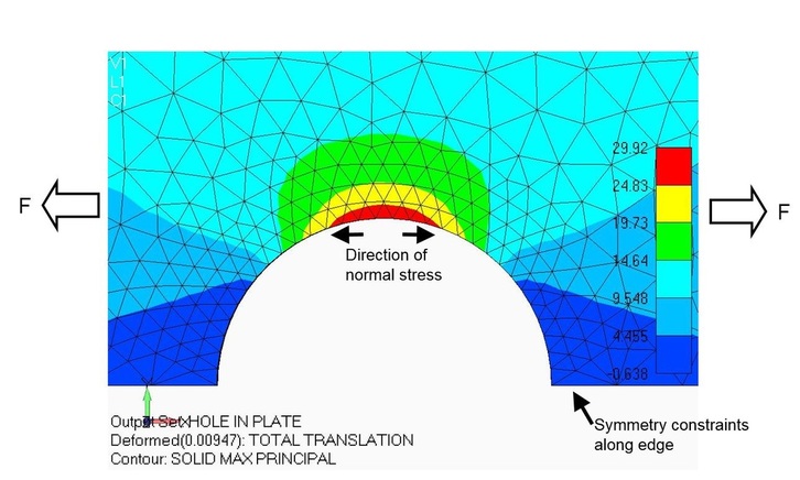
The maximum principal stress from the FEA is 29.92 MPa. Compare this with the hand calculation of 28.22 MPa. Both methods are reasonably close.
Tip
The maximum principal stress is in the same direction as the normal stress in this case. Also the mesh density will affect the FEA results.
Tip
The maximum principal stress is in the same direction as the normal stress in this case. Also the mesh density will affect the FEA results.