Coordinate Systems used in FEA
There are three types of 3D coordinate systems used in FEA and they are cartesian, cylindrical and spherical.
The cartesian and cylindrical coordinate system is commonly applied to most analysis models. In practice the spherical coordinate system is rarely used.
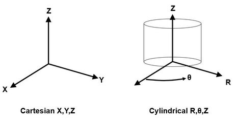
A single unconstrained node in space has 6 degrees of freedom. When using a cartesian coordinate system this means it can translate in X, Y and Z . It can also rotate about X, Y and Z. So to apply a constraint to a point in X and Y will allow the point to slide up and down the Z axis only.
For a cylindrical coordinate system a single unconstrained node can translate axially along Z, translate radially along R and swing circumferentially about θ. So to apply a constraint to Z and R will allow the point to move in θ only.
These coordinate systems are important for setting up loads, boundary conditions and checking the results. Typically cylindrical co-ordinate systems are used for cylinders, tubes and shafts.
Sometimes translation in X,Y and Z is referred to as DOF 1,2,3 and rotation about X, Y and Z as DOF 4,5,6. So a fully constrained point would have all six degrees of freedom fixed. i.e. DOF 1-6.