- Value Design Ltd
- Services
- Projects
-
Finite Element Analysis
- Introduction to Basic FEA
- Units
- Co-ordinate Systems
- FEA Procedure
- Defining Objectives
- Stress Concentration
- Geometry import / clean up
- Meshing
- Material Properties
- Boundary Conditions
- Solvers
- Investigating FEA Results
- Reporting
- Stress Theories
- Cantilever Beam Worked Example
- Pressure Vessel Worked Example
- Shaft in Torsion Worked Example
- Buckling Worked Example
- Bearing (Contact) Worked Example
- Non Linear Material Worked Example
- Portal Frame Worked Example
- BLOG
- FAQ
- CONTACT
|
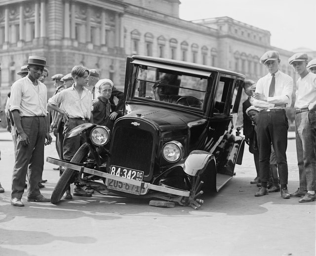
There are so many reasons engineering components break, I've seen quite a few and here is my top ten list. There must be many others that I've missed. I've always said that the best way to learn about engineering and in particular finite element analysis, is to study components that have already broken. 1. Stress Concentrations Now for ductile materials such as steel, this is of concern for durability but not for overall strength. However, brittle materials such as grey iron tend to crack in areas of high stress concentration even for single loading events. 2. Weld Fractures A lot of component failures are due to welding since no two welds are the same. Welds situated too close to each other, in the wrong place, the wrong size or of poor quality are the main culprits of failures. 3. Selecting the Wrong Material Some people switch to a cheaper grade of material in an effort to reduce cost without revisiting the calculations or FEA. Some materials do not fare well when exposed to high or low temperatures, corrosive substances or high cyclic loading. 4. Skipping FEA or Calculations to Save Time Guessing component sizes is a tempting gamble to speed up the project and reduce initial development costs. A gamble that usually costs the project dear! 5. Using the Wrong Design Code and Standards Treat mobile machinery like a building if you want but it will probably break. Buildings don’t move and they don’t bump into things. Don't use a building design code for cranes, use a crane code. Use the right design code! 6. Sweeping the Hard Load Cases Under the Carpet Checking the easy load cases and ignoring the the difficult ones that really could break your components is more common than you think. It's nearly always the tricky load cases that are hard to define that are the main culprits for component failures. 7. Stripping Out Too Much Material Optimising your components for reduced weight to strip out excessive margins of safety is what all we all want. Components often fail due to fault load cases that may not have been considered because they were unknown at the time. Leave a safety net! 8. Relying on a Single Load Path Designing components with a single load path is asking for trouble! Hanging large weights on a single bolt or weld is never a good idea. Would you stand underneath it? 9. Poor Quality Control Poor quality castings and incorrect heat treatment without proper quality control are prime suspects. There are lots of design codes and manufacturing standards that should be followed. 10. Lack of Physical Testing FEA Analysis and other CAE tools are great but to validate designs, some component testing is often still required. Skip this at your own risk! There are lots of other reasons parts fail, I'm interested to hear of your experiences with component failures and what you did to fix it?
3 Comments
Linda Cole
8/24/2021 05:51:28 am
Nice article
Reply
Ramin
9/1/2021 06:52:59 pm
Perfect,
Reply
Chris Hall
9/2/2021 12:45:12 am
Thanks, I agree. Your comment will be posted after it is approved.
Leave a Reply. |
AuthorChris Hall Categories
All
Archives
May 2023
|
- Value Design Ltd
- Services
- Projects
-
Finite Element Analysis
- Introduction to Basic FEA
- Units
- Co-ordinate Systems
- FEA Procedure
- Defining Objectives
- Stress Concentration
- Geometry import / clean up
- Meshing
- Material Properties
- Boundary Conditions
- Solvers
- Investigating FEA Results
- Reporting
- Stress Theories
- Cantilever Beam Worked Example
- Pressure Vessel Worked Example
- Shaft in Torsion Worked Example
- Buckling Worked Example
- Bearing (Contact) Worked Example
- Non Linear Material Worked Example
- Portal Frame Worked Example
- BLOG
- FAQ
- CONTACT


