- Value Design Ltd
- Services
- Projects
-
Finite Element Analysis
- Introduction to Basic FEA
- Units
- Co-ordinate Systems
- FEA Procedure
- Defining Objectives
- Stress Concentration
- Geometry import / clean up
- Meshing
- Material Properties
- Boundary Conditions
- Solvers
- Investigating FEA Results
- Reporting
- Stress Theories
- Cantilever Beam Worked Example
- Pressure Vessel Worked Example
- Shaft in Torsion Worked Example
- Buckling Worked Example
- Bearing (Contact) Worked Example
- Non Linear Material Worked Example
- Portal Frame Worked Example
- BLOG
- FAQ
- CONTACT
|
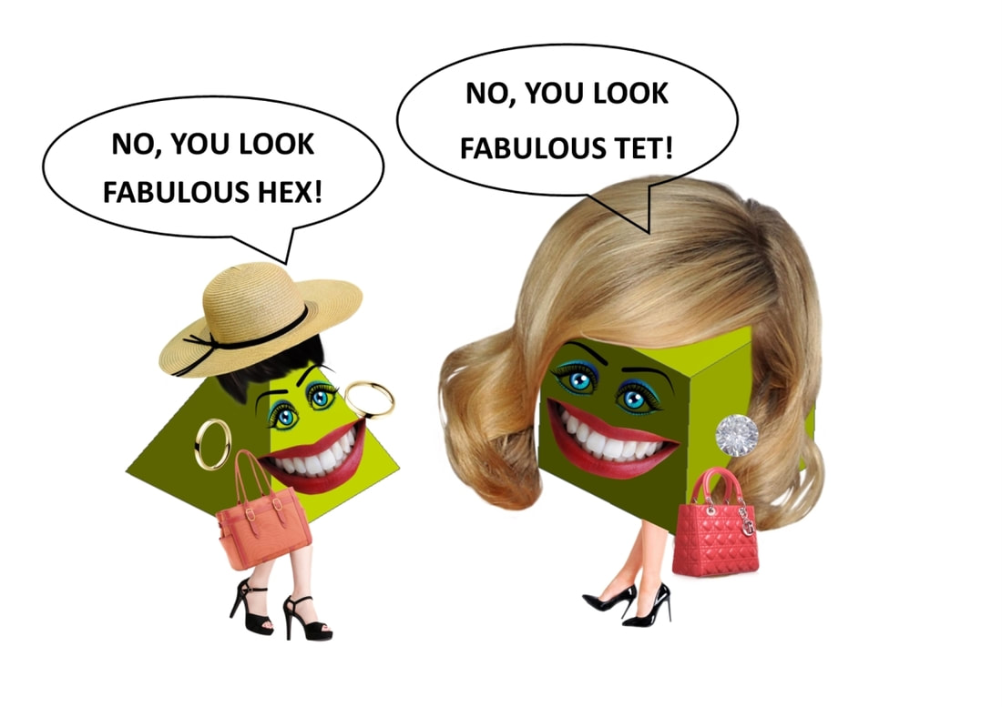
Hex and Tet are what you call frenemies, they are friends but are secretly jealous of each other and green with envy. It was Saturday night and their boyfriends were watching football, so they decided to go on a girl’s night out. Hex had put on few pounds and was a little self-conscious about it so she wore a modest outfit that accentuated her shape. “You look fabulous, have you lost weight?” Tet says with a wry smile whilst looking Hex up and down and fluttering her eyelashes. Tet used to have long flowing hair but recently tried a new shorter hair style, she didn’t really like it so she wore a fashionable hat to hide her mistake. “No, you look fabulous, I love your new shorter hair style” Hex says flicking her long shiny locks of hair over her shoulders. She then twirls her hair around her fingers. “It must be so much easier to manage” she says with glee. So, what’s all this got to do with finite elements….................... There is a lot of debate and a bit of rivalry in the FEA Analysis world about which is better Tetrahedral or Hexahedral elements. The ‘experts’ tend to favour Hex elements and like to build beautiful meshes. The ‘novices’ usually favour Tet elements because they’re easy to mesh most CAD geometry. I have listed the Pros and Cons of each and later compared the performance with worked examples. Tetrahedral Elements Pros
Hexahedral Elements Pros
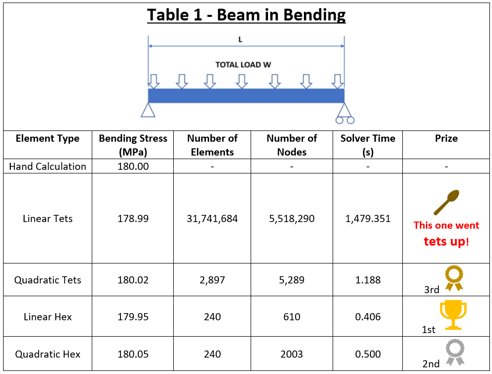
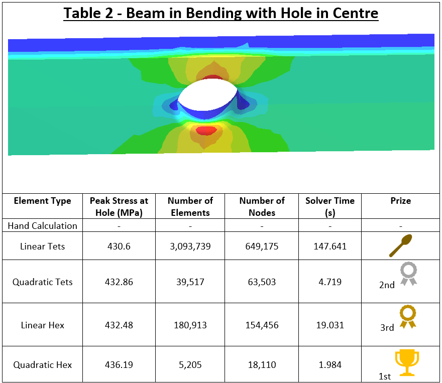
Worked Example Tet vs Hex To put this to the test, consider a simply supported beam with pinned ends. The results are compared to about 99% convergence with Quadratic and Linear Hex and Tet elements. The beam is 3000 mm long by 200 mm wide and 50 mm deep. The total distributed load is 40 kN. The results are shown in Table 1. The analysis was then repeated with a hole in the centre of the beam to save weight (bad joke 😊) and this is presented in Table 2. You can see from the results that both Hex and Tet elements have many similarities in performance, apart from Linear Tets which are best avoided if possible. I’m sure that some of you experts out there could mesh the models to create a different outcome but I didn’t have the time to optimise the meshing.
With highly non-linear models, it may be worth putting in the extra effort to create a beautiful Hex mesh because of hardware constraints or to reduce solver time for larger models. On the other hand, geometry with lots of small features and fiddly bits may take too long to mesh with Hex elements. In those cases, Tet elements may prove to be a better option. Back to Hex and Tets girls’ night out…….......... After all of the rivalry, Hex and Tet have more in common than they expected and they really enjoyed their night out. Tet then pays a visit to the Ladies Loo and her phone rings. It was her other friend Tri. “Hi Tri, guess what? I’m out with Hex” Tet says with a weary voice, slightly worse for wear. Tet sighs, rolls her eyes, then says “She’s really getting on my TETS!”
4 Comments
Aaron Alex Lopes
7/21/2022 09:03:05 am
Awesome explanation. I am an amateur in FEA, I am pursuing my masters in Computational Mechanics and have learned a lot of FEM, derivations and so. But I lack a lot of info regarding the commerical FE Softwares.
Reply
Chris Hall
7/21/2022 09:10:26 am
Thanks for the kind words, I’m glad you liked it.
Reply
Haris Malik
3/16/2024 11:36:19 am
From where do you get the number of elements for linear tets to be 31 million plus. It is generally acceptable that tets are little worse than hex but not by the margin you are writing in this blog
Reply
Chris Hall
7/10/2024 12:00:07 pm
I meshed it with 31 million elements to prove a point. Linear tets are much worse than parabolic tets, not a bit worse, much worse and they should be avoided.
Reply
Your comment will be posted after it is approved.
Leave a Reply. |
AuthorChris Hall Categories
All
Archives
May 2023
|
- Value Design Ltd
- Services
- Projects
-
Finite Element Analysis
- Introduction to Basic FEA
- Units
- Co-ordinate Systems
- FEA Procedure
- Defining Objectives
- Stress Concentration
- Geometry import / clean up
- Meshing
- Material Properties
- Boundary Conditions
- Solvers
- Investigating FEA Results
- Reporting
- Stress Theories
- Cantilever Beam Worked Example
- Pressure Vessel Worked Example
- Shaft in Torsion Worked Example
- Buckling Worked Example
- Bearing (Contact) Worked Example
- Non Linear Material Worked Example
- Portal Frame Worked Example
- BLOG
- FAQ
- CONTACT


